ANSA ARROW IV HEAVY LIFT VEHICLE
SERIES VII SURFACE TO ORBIT BOOSTER
FULLY
STAGED HEAVY LAUNCH VEHICLE
![]()
INDIVIDUAL STAGE COMPONENT |
DESCRIPTION |
FULLY STAGED VEHICLE |
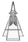
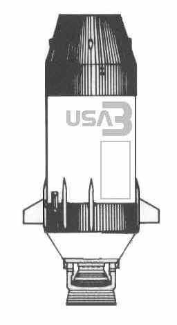
"TOWERJET"  EERS EMERGENCY The EERS or "Tower-Jet" is a simple precautionary measure safety device designed to be used if a problem occurs before or during initial launch. The four solid fuel rockets will provide enough thrust to lift the "Icarus" Primary Command Module (PCM) away from the main lifting body and allow the command module to return to Earth at a safe distance away from the launch pad.
|
The EERS has no control surfaces of its own, it relies wholly on the integral aerodynamic design and the canards of the "Icarus" command module to provide any aerodynamic control and course correction during an emergency jettison option. The individual jets can be 'steered' by input commands sent through the EERS flight control computer in order to adapt its thrust and vectors to fully utilize the aerodynamics of the command module. The EERS' chemical fueled rocket pod provides twenty-five seconds of rapid fatigue thrust, enough power to lift the "Icarus" series command module free of the heavy lift vehicle and to propel it safely away from any danger in the event of a launch emergency. During a pre-launch emergency, activation of the EERS can be initiated either by the crew or if the crew is incapacitated then the EERS can be activated by ground control. Activation of the EERS during pre-launch conditions also detonates the explosive bolts holding the "Icarus" capsule to the heavy lifting body. The EERS is normally jettisoned at high altitude, along with Stage Four, during a stepped launch. At that altitude, the "Icarus" itself is capable of a crew initiated and crew controlled gravity assisted landing to a wide number of safe recovery sites. |
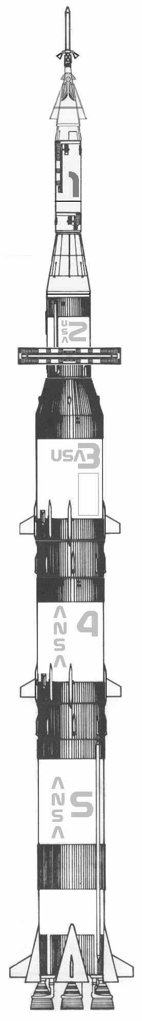
The composite diagram below depicts all components of the ARROW IV HEAVY LIFT BOOSTER assembled for launch and the completed vehicle ready to be carried via heavy tracked crawler to Launch Complex #39 at Kennedy Space Flight Control Center in southern Florida. Fueling of all components and final systems checks will be carried out once the vehicle is secured to the launch pad and gantry system. Uplink to onboard systems is conducted via dedicated utility and umbilical trunks attached to service ports at each stage of the vehicle. Mission Control monitors the upload of mission critical data to the onboard systems, as well as the downlink and diagnostics of all integrated systems throughout the pre-launch and well until after launch. |
| ANSA
American National Space Administration
ICM Series spacecraft
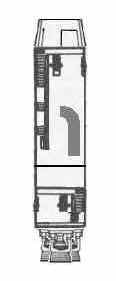
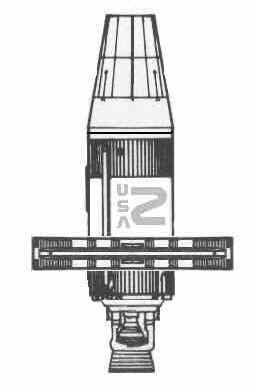
COMMAND MODULE "Icarus" Sister ships in the ICM series "Damocles" "Prometheus" "Atalanta" The ICM "Icarus" command module is used for circumferential flight control, post-mission reentry and post-mission astronaut retrieval at the end of the flight. |
The command module design includes limited life support, basic flight instruments and flight controls, emergency survival gear, the flight recorder / mission log systems, and four suspended animation chambers. During the long flight, the ICM will also serve a forward observatory since the view ports afford a large view of the forward approach of the spacecraft. Primary flight mission functions are handled in the command module which draws its control and command functions from its link to the main computers and flight control systems located in Stage One. Most flight systems are duplicated for safety reasons. The crew will spend a large amount of time in the command module, both during waking time and during hibernation periods. The ICM, when connected to Stage One, forms the total command nucleus for the mission flight. Once separated, the "Icarus" command module is little more than a lifeboat designed to return the four astronaut crew safely back to Earth and to splash down in the ocean for rendevouz with naval spacecraft recovery and rescue crews. |
CREW
LIFT OFF POSITIONS
|
 |
STAGE
ONE PRIMARY CONTROL Stage One is the premier C3 element of the "Icarus" flight system. The powerful Texas Instruments "Gibraltar" series of main frame flight relay arrays is located in this section, along with extensive data banks, mission data recording capacity, and a backup computer system. Batteries and deployable solar power arrays supply emergency power in the event of a systems failure. The commons is located in Stage One, along with the head, shower, emergency medical station, a flight data lab, and both the primary and secondary air lock system. Full EVA equipment is included as well as survival and medical supplies. All scientific equipment is carried in this section, stored in protective cases and located so as to provide the maximum amount of space to the crew. |
|
 |
STAGE TWO DAEDALUS ATSOL DRIVE AND GRAVITY FIELD GENERATOR ARRAY Stage Two contains the primary Mark III Lycoming Teledyne Rand stellarator nuclear reactor as well as the gravity field generators which will not only mold and shape the nuclear plasma produced by the Daedalus fusion pulse drive but also produce the anti-acceleration fields which protect the crew. The drive is completely automated, linking the drive section with Stage One allows the crew and computers to remote control the operations of the ATSOL (Approaching The Speed Of Light) capable gravity ring drive system. Under power, the gravity ring drive system projects a biased field of 'positive' gravity and 'negative' gravity, at opposite ends of the ship. To accelerate the ship, negative gravity is produced at the front of the vessel and positive gravity at the rear, the ship then 'falls' forward into its own gravity shunt, faster and faster. Deceleration is accomplished merely by reversing the polarity of the two fields, causing an inverted drag effect to occur. The ring field generator assembly is also used to regulate the flow of the plasma used as thrust. Another function of the field generator is to provide one standard gravity for the crew to work in during the long flight as well as provide a 'fixed reference' of gravity at all times and all orientations of the vehicle. Internal gravity is shut down to conserve power during times of crew suspended animation. Micro-gravity is maintained at one standard G inside the suspended animation chambers. |
|
 |
STAGE THREE- PRIME BOOSTER Stage Three is the last of the chemical fueled boosters. The fins are used to control flight, rotating slightly on powered mounts as aerodynamics require. Stage Three is the prime booster, lifting Stage Two, Stage One, and the command module into the upper reaches of the atmosphere. After the vehicle has cleared Earth gravity, Stage 3 will give it the final boost out into deep space. At a distance of twelve thousand miles from Earth, Stage 3 is jettisoned. |
|
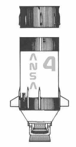 |
STAGE FOUR- SECOND BOOSTER Stage Four is the second of the primary chemical fueled boosters. The docking ring for Stage Two and Stage Three is explosively blown away seconds before the main ignition of Stage Three. The variable pitch venturi nozzle of Stage Two allows the onboard flight control systems of the vehicle to adjust total driving thrust according to payload demands during all aspects of the stage burn. |
|
|
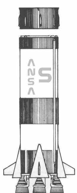
STAGE FIVE- MAIN BOOSTER Stage Five is the primary surface lifting booster assembly providing primary and initial surface escape power. The five primary turbo-pulse FJ2 engines consume 20 tons of fuel per second, the five variable venturi nozzles adjust their thrust apertures several times a second to tailor the generated thrust to aerodynamic drag and flight profile. Over one hundred aeronautical flight sensors are included in the design of Stage Five, all feeding information to the onboard flight control computer system during the life of the booster stage. Stage Five provides initial thrust as well as motive power for the other flight components. Stage Five is the heaviest of all the vehicle components and takes the most time to fuel. It is also the most dangerous component and is the one that is most closely watched by mission and flight control operators. A critical failure with any component of Stage Five could bring catastrophic destruction not only to the vehicle, but also to most of the launch facility.
|
![]()
Questions or comments?
EMAIL ANSANAUT